NOTE: The assembly instructions below are for assembly with screws. Most of the same strategy can be used with assembly by staple gun. The staple gun is how the original cabinets were assembled and is a much quicker process.
Assembly Time ~5+ Hours
The assumption is that all of the pieces have already been cut and that T-molding has been already installed. In the assembly described below, we are using Melamine. Melamine is a great material to work with since it is already "finished". The down side is that melamine chips easily when cut and if the ends are "bumped" during assembly. This is why I cut and apply T-molding as soon as possible, and prior to assembly.
|
Materials
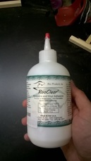
1. Cut panels with T-molding applied as needed 2. Roo Glue for Melamine (R1GI4) 3. Kreg Screws (SMC-C125) pocket screws coarse thread 4. 7/8" Black Melamine edge banding 5. Feet / Sliders / Casters 6. Paper Towels |
Tools
1. Work Bench / Saw horses 2. Power Drill 3. Kreg Jig Master System (K4MS) 4. Table Saw 5. Hand Sander 6. Table Top sander 7. Assorted clamps 8. Measuring Tape 9. Marking device (Pen / Pencil / Silver Sharpie) 10. Metal square |
I apologize for the bad pictures. I couldn't find my good camera and was stuck taking pictures with my camera phone.
Starting out, the guide is assuming that all of the parts have been cut with respect to the plans and all of the T-molding has been installed.
NOTE: If you are going to assemble the cabinet with screws (like this guide), it is important that you cut your T-molding slot prior to assembly. The slot cutter cuts much deeper then is necessary for the T-molding. The depth of this cut can interfere / make contact with the Kreg screws and will destroy / damage your slot cutter. This is why I install the T-molding prior to assembly. It also helps to protect the panels.
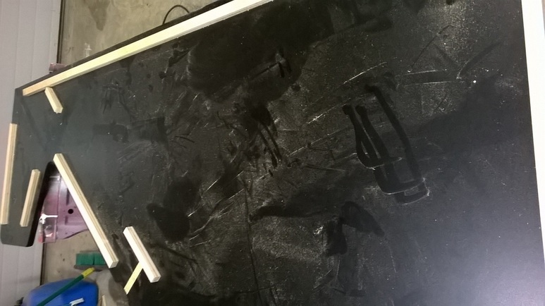
1. I start out the assembly process by placing a side of the cabinet on my work benches / saw horses for assembly with the inside of the cabinet facing up.
2. Next, I gather up all of the pre-cut blocking strips. I lay out the blocking strips across the panel to make sure I have them all and that they fit in shallow dado cut for them.
NOTE: If you are going to assemble the cabinet with screws (like this guide), it is important that you cut your T-molding slot prior to assembly. The slot cutter cuts much deeper then is necessary for the T-molding. The depth of this cut can interfere / make contact with the Kreg screws and will destroy / damage your slot cutter. This is why I install the T-molding prior to assembly. It also helps to protect the panels.
1. I start out the assembly process by placing a side of the cabinet on my work benches / saw horses for assembly with the inside of the cabinet facing up.
2. Next, I gather up all of the pre-cut blocking strips. I lay out the blocking strips across the panel to make sure I have them all and that they fit in shallow dado cut for them.
NOTE 1 on the blocking: On the drawings, I have blocking drawn in place. In most of the drawings, I have the blocking / dado width set at .80". I cut blocking that is .75" wide and is .05" shorter then the length of the blocking. This usually allow for easy installation. The blocking I cut is not part of the drawings since I am tying to minimize confusion while cutting a cabinet.
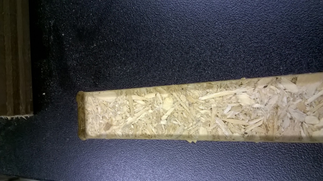
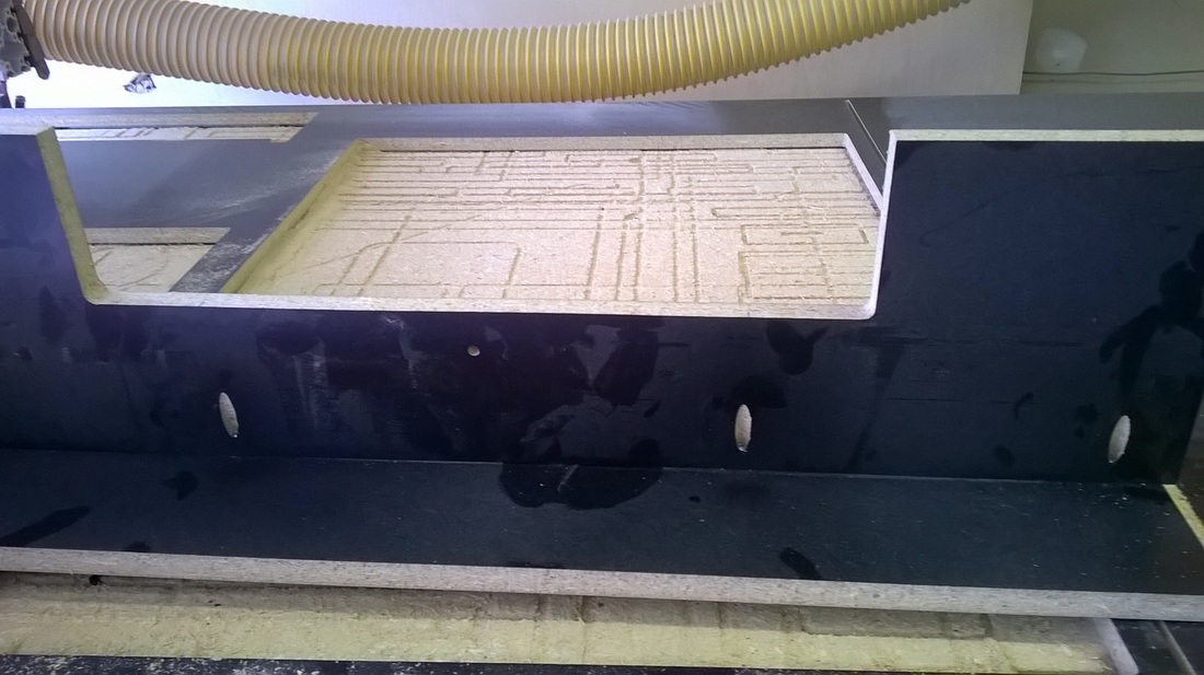
NOTE 2 on blocking: All of the dado cuts are at a depth of .10". This is just deep enough to mark for placement and to add a little strength to the joint, without taking away from the height of the blocking. All of the dado cuts are with "dog bones" (see pictures). The dog bones are to allow the blocking to be installed and for the blocking to have sharp (pointed) corners.
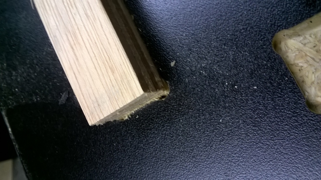
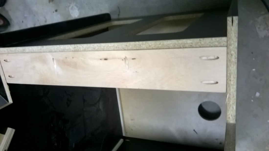
The picture below show the dado joint with the dog bone cut. The second picture shows the dado joint with the blocking dry fit in place. The small amount of chipping that can be seen in the first picture is the result of using the wrong router bit to make the cut. I use a Whiteside 2102 bit (compression bit) to cut my panels. The bit tends to cause chipping on cuts less then .25" deep. If I wanted a cleaner edge, I would use something that has a downward spiral. In this case, I don't believe the chipping will matter since it is on the inside of the cabinets and will be covered with other panels once assembled.
NOTE 2 on blocking: All of the dado cuts are at a depth of .10". This is just deep enough to mark for placement and to add a little strength to the joint, without taking away from the height of the blocking. All of the dado cuts are with "dog bones" (see pictures). The dog bones are to allow the blocking to be installed and for the blocking to have sharp (pointed) corners.
The picture below show the dado joint with the dog bone cut. The second picture shows the dado joint with the blocking dry fit in place. The small amount of chipping that can be seen in the first picture is the result of using the wrong router bit to make the cut. I use a Whiteside 2102 bit (compression bit) to cut my panels. The bit tends to cause chipping on cuts less then .25" deep. If I wanted a cleaner edge, I would use something that has a downward spiral. In this case, I don't believe the chipping will matter since it is on the inside of the cabinets and will be covered with other panels once assembled.
|
|
|
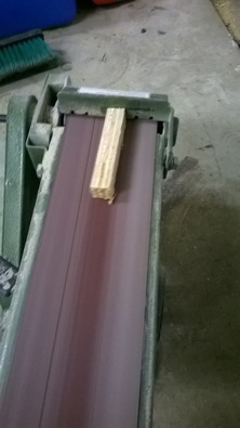
3. Next I sand all of the blocking. This will help to improve fitment and will give a cleaner overall appearance to the inside of the cabinet. In this case, I used some lower grade sanded plywood (pine) for blocking. The top coat tends to fray / splinter when cut and needs some cleaning up prior to assembly.
NOTE: For the assembly of these cabinets (I am not sure it matters) I have started to use plywood for all of my blocking. Structurally it is much stronger then melamine. In the case of the Konami 4P cabinets, I usually only use the blocking for placement or panels and are primarily not structural in nature... I still don't think it is a bad idea. |
|
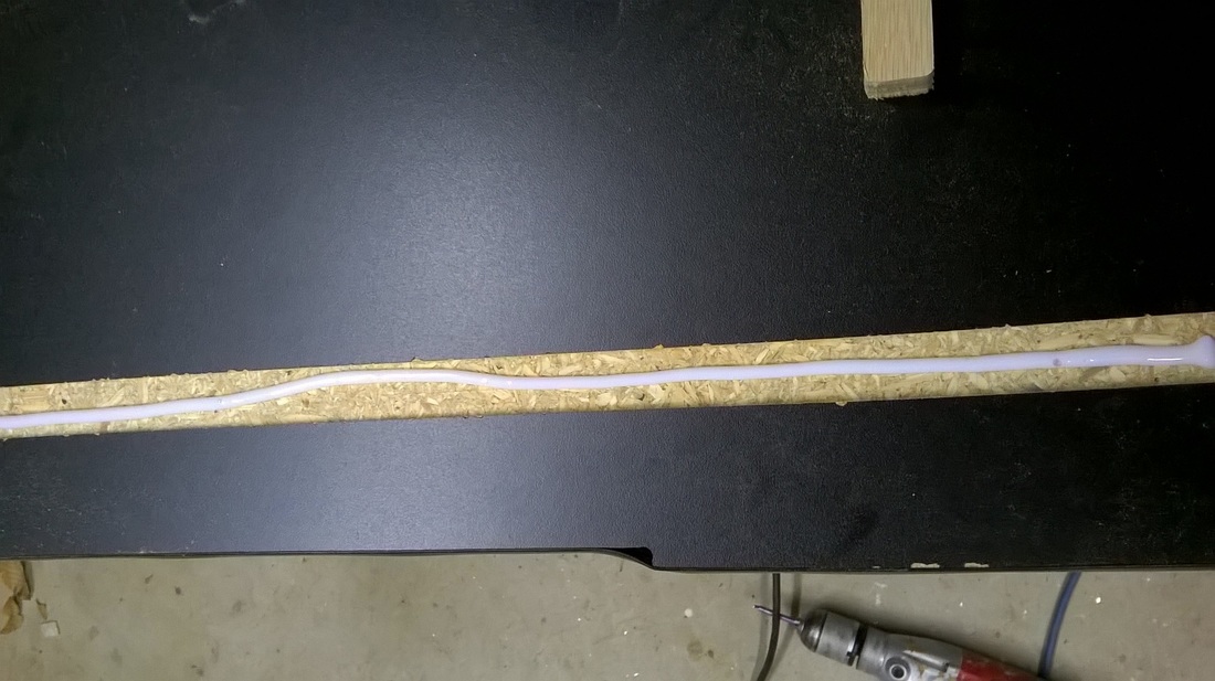
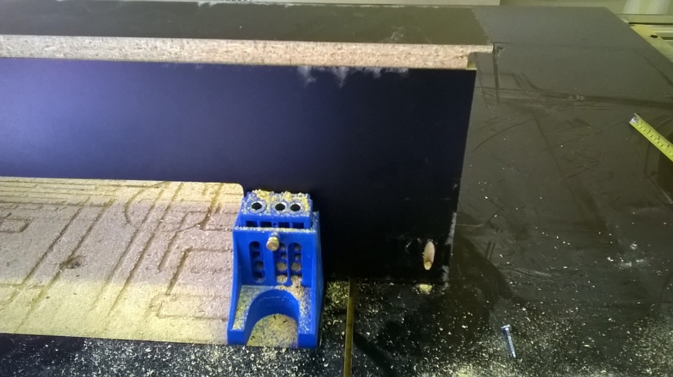
4. With all of the blocking sanded and dry fit, I now start to install the blocking. First a layer of Roo glue (great stuff... specifically designed for melamine. Conventional glue will not stick to the smooth surfaces of melamine), placement of the blocking, and then a few 1" Kreg course screws to lock everything in place.
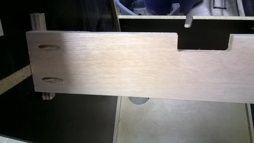
NOTE: When installing the blocking, you want to have the grain side of the plywood facing up, not the plywood side (see pictures). If the ply side is facing up when you go to screw down the blocking, it will split when screwed down...especially if over tightened.
NOTE: When installing the blocking, you want to have the grain side of the plywood facing up, not the plywood side (see pictures). If the ply side is facing up when you go to screw down the blocking, it will split when screwed down...especially if over tightened.
|
|
|
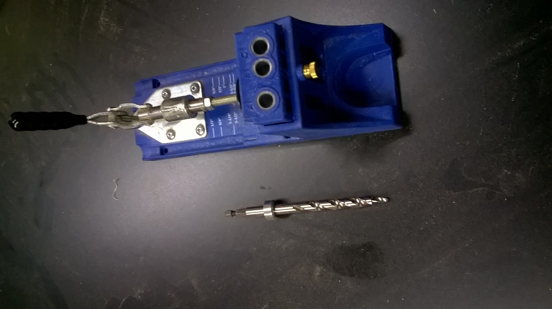
NOTE Kreg Jig: I have started to used screws and the Kreg Jig in the assembly of all of the cabinets I build. I know this is not the method originally used for assembly, but I feel it results in a higher quality end product. I believe the screws offer a stronger joint that tends towards being more "square" then assembling with blocking and staples. The screws also allow for more "forgiveness" during assembly. Additionally, if the cabinet has art that is applies to the front panel, this can easily be applied since the front panel can be removed (such as Galaga).
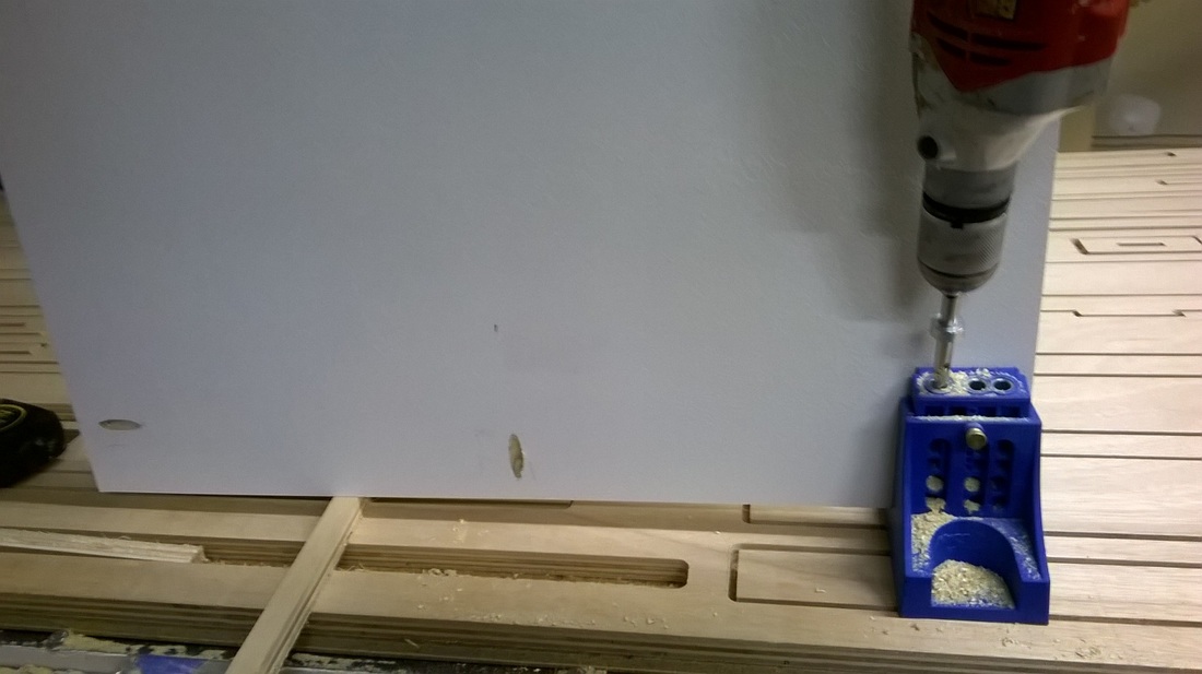
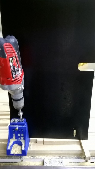
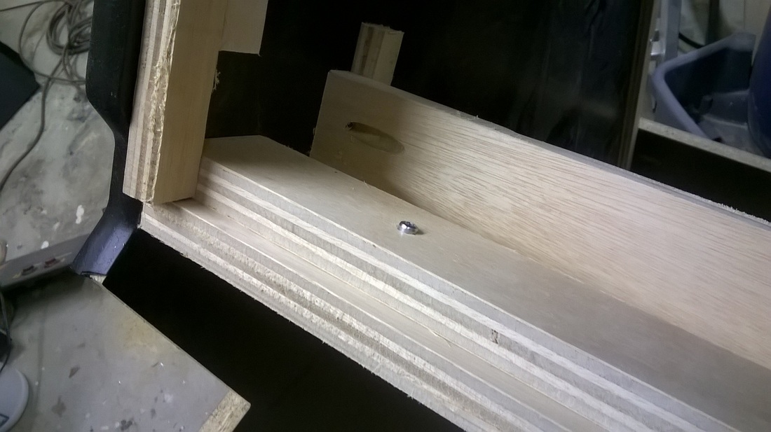
5. Using the Kreg jig, I cut pocket holes for assembly. This can be done without too much though/calculation with this cabinet due to the joint construction. Any cabinet being put together with dado and rabbet joints need additional planning before cutting. I start out cutting the pocket holes on the base of the cabinet. On this panel, I cut the pocket holes to be on the bottom of the cabinet. This is done for two reasons.
5. Using the Kreg jig, I cut pocket holes for assembly. This can be done without too much though/calculation with this cabinet due to the joint construction. Any cabinet being put together with dado and rabbet joints need additional planning before cutting. I start out cutting the pocket holes on the base of the cabinet. On this panel, I cut the pocket holes to be on the bottom of the cabinet. This is done for two reasons.
|
A. When assembling anything with the Kreg screws, the panel being attached tends to travel in the direction of the screw. By placing the pocket holes on the bottom of the panel, it will cause the base panel to move up and into the blocking already present on the side panel of the cabinet. This will result in a nice a straight edge to build the rest of the assembly on. B. I think you get a cleaner looking cabinet by having the pockets not being visible on the bottom of the cabinet to collect dirt. |
For the base, I usually drill 3-4 pockets a side. In the case of the Konami 4P style cabinet, the base is covered on all sides. Some cabinet designs leave the base visible from from the back of the cabinet. In this case, I would only drill holes on the base on 3 sides, and I would drill an additional set of pocket holes on the back base to attach with the base. The idea is to make sure that every joint surface has at least 2 screws securing the joint.
|
|
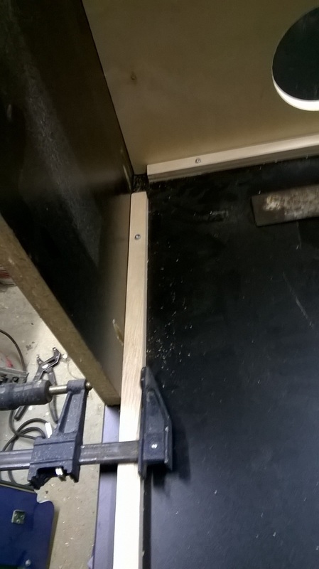
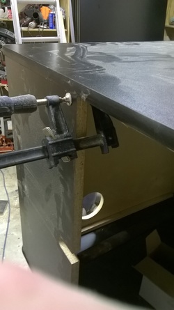
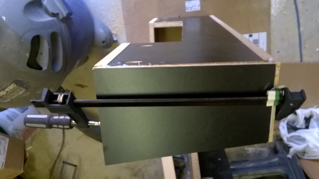
6. Next is to attach the base to the side panel of the cabinet to star assembly. I apply a layer of Roo glue to the edge of the blocking and the edge of the melamine where the panel will be placed. I line up the base with the edges to be mounted (see picture) and I clamp the panel to the pre-installed blocking.
Using a metal square, I align the base panel to the side of the cabinet and install the 3 screws, starting at the edge with the square. Once 2 of the screws are in place, the base should be free standing.
Using a metal square, I align the base panel to the side of the cabinet and install the 3 screws, starting at the edge with the square. Once 2 of the screws are in place, the base should be free standing.
|
|
|
|
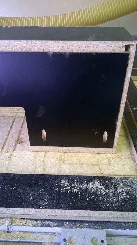
7. Next will be to cut the pocket holes on the back base of the cabinet. In this case, I am only cutting 2 holes per side. The back base then will get clamped to the blocking. Particular attention needs to be paid to the alignment of the panel to the base. All of the assembly is based around squaring everything up to the base of the cabinet. Glue is used as well for assembly.
|
Cutting Pocket Holes
|
Clamping panel to the blocking
|
Aligning the panel to the base of the cabinet.
|
|
8.
|
|
9. Next is the pocket hole drilling for the front of the cabinet and assembly. The important thing is to make sure the top of the front panel lines up with the cabinet correctly for the placement of the control panel.
Same as with the back base, you install the three screws between the front panel and the side of the cabinet and then install only the bottom screw between the front and the base.
Same as with the back base, you install the three screws between the front panel and the side of the cabinet and then install only the bottom screw between the front and the base.
|
|
10. Now it is time to install the other side panel to the cabinet. Before you start, you need to have all of the blocking installed and secured on the side panel (Steps 1 thru 4).
Find some help... if you can...
In my case, I have no help available , so I position the speaker panel (at the top of the cabinet) and support it with something heavy. I then lift the other side panel and try to align it as best I can and make sure it is supported and isn't going to fall.
Stepping back, I make sure all of the blocking is on the inside (correct side) of the panels. I then install the screw closest the top of the front panel while making sure the side panel and top front stay flush with each other.
|
|
|
|
11. The screws Install in the following order.
|
A. Base top. Making sure the base is flush against the blocking, I install the screws in the base and the top (new side panel) I make sure my alignment is correct between the front panel and the back base. B. Base / Front. Next set of screws go in are between the base and the front. These screws (when tight) will help to keep the front in position while installing the two remaining screws. C. Front / Side panel. These screws go in next. The are supported now by the base, so they should not drift or move without clamping. D. Back base. Install the two remaining screws in the back base. As usual, clamp when you can. |
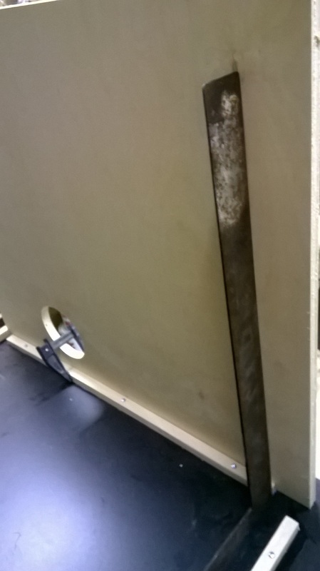
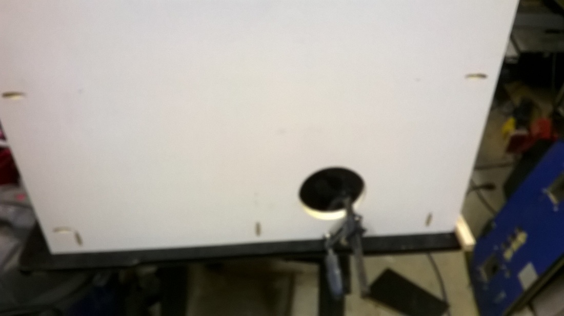
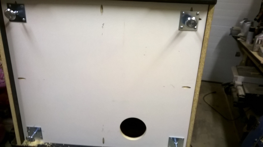
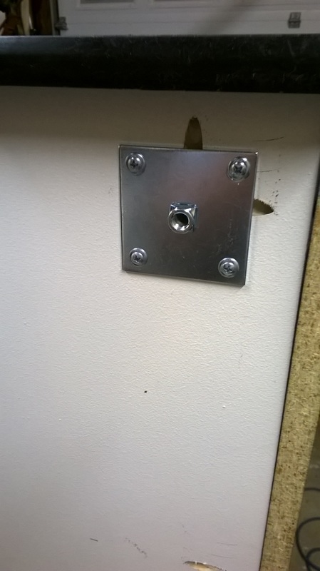
12. Next up is the installation of the feet. Personally, I like the metal plates to be installed as supports. I feel these are much stronger and are a better solution over what factory offered. If you are going to not use the metal plates, make sure you drill your holes in a way that will not structurally "weaken" the base or cause the feet to fail.
|
|
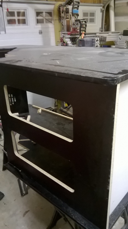
13. Lucky step 13. From here it is time to stand up the cabinet. Get help if you can. I'm a big guy and it is an awkward struggle for me to pick up the cabinet by myself and get it to the floor without damaging something.
|
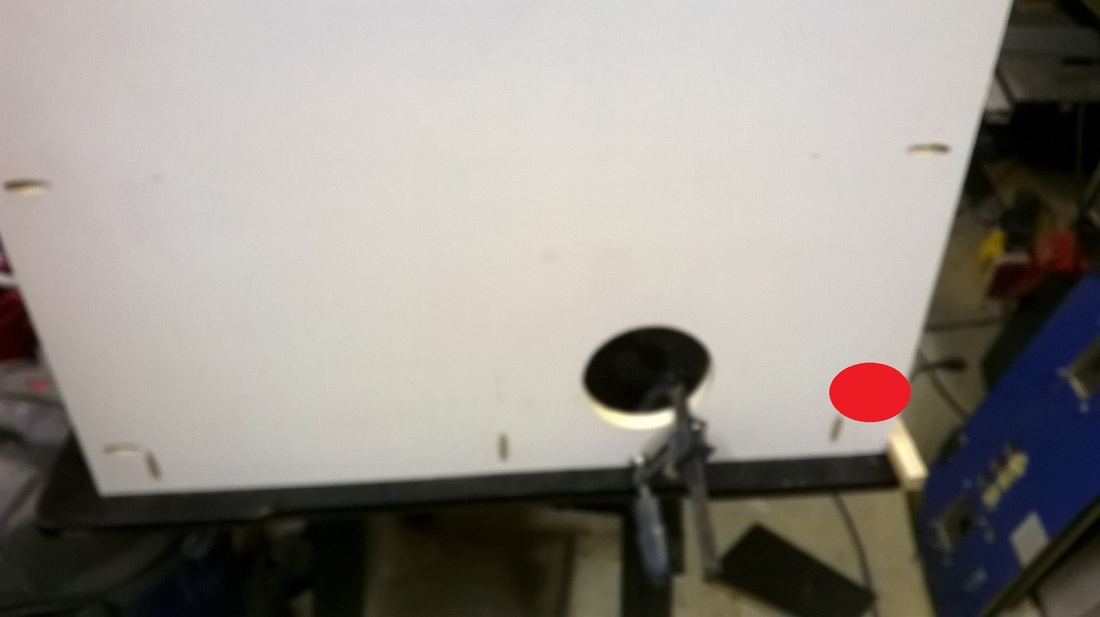
For the top of the cabinet, I drill 3 pocket holes per side. and align the top panel with the back of the cabinet. It is very important you get everything lined up and flush on the top of the cabinet. This will impact how square the cabinet is when you are all done. 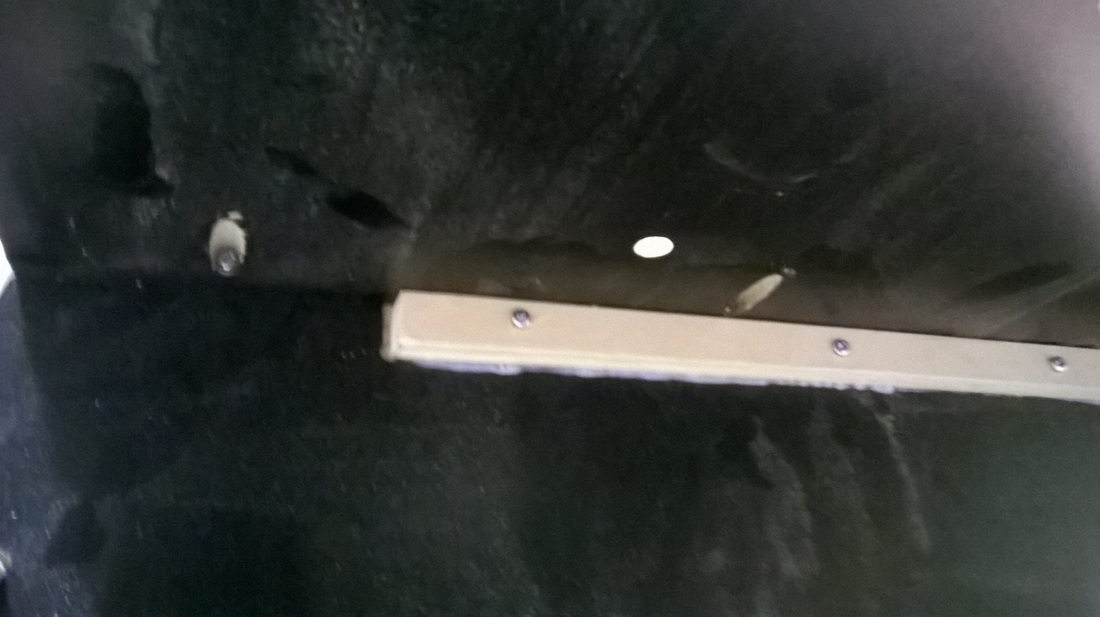
|
|
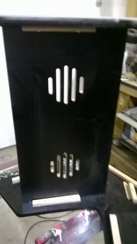
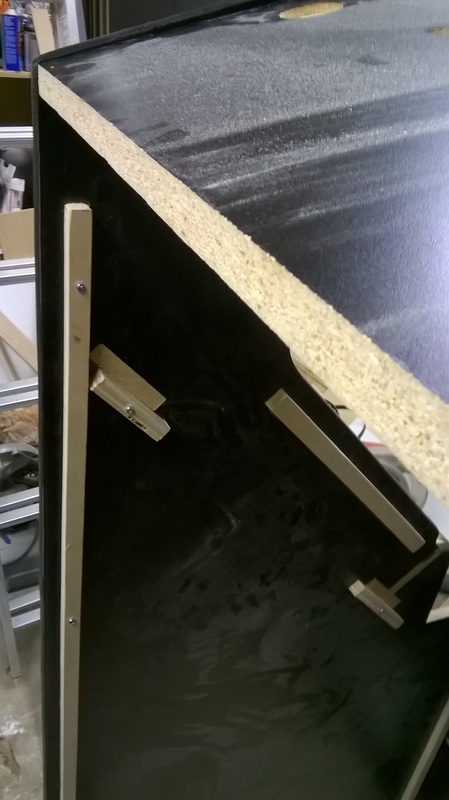
14. Next comes the installation of the speaker panel. The panel is drilled with only 2 holes per side, and the holes are a little closer to the edges of the panel. This is done to allow enough space for the drill to be able to get in and install the screws.
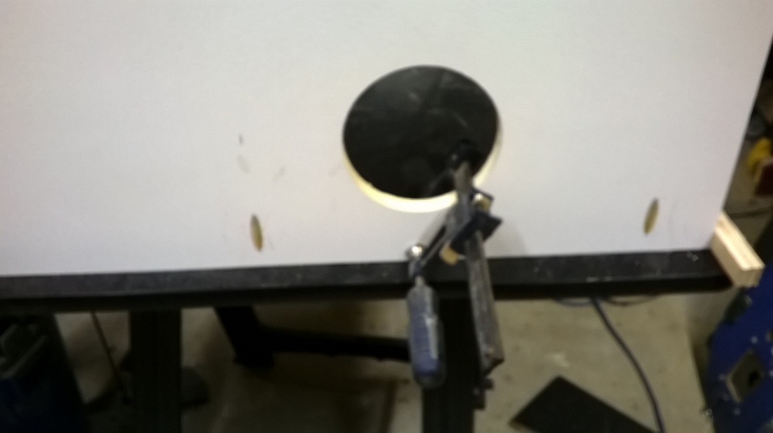
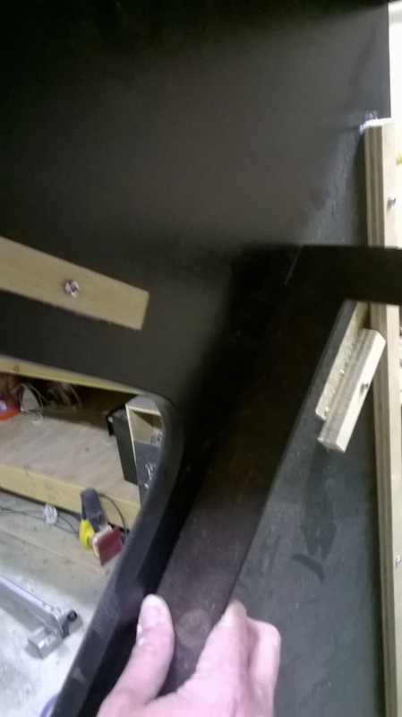
Next, I need to mark placement of the speaker panel. In this case, it is particularly important to get the placement correct so that the monitor class will fit. What I do is place my metal square along the guide for the the monitor glass and trace the top edge (difficult to see in the picture below).
Ideally with help, someone holds the speaker panel in place while you get the screws in.
|
|
15. The final piece to assemble on the outside of the cabinet is the top back. As I go to install this piece, I will loosen the screws by hand on the top and speaker panel (The top back will not even clear the T-molding until this is done). The top back is installed and needs to be flush with the top. This is really important because it helps to square up the cabinet and top. Once it is in place and clamped down, I re-tighten all of the screws for the top and speaker panel... and then install the screws for the top back.
|
|
16. Next is the assembly of the internal structure for the monitor and cross supports. All of these pieces have 2 pocket holes at each end, and when possible have pocket holes that tie each other together.
The blocking that we previously installed and glued down in step #4 are primarily used as guides for placement and are not weight bearing. With that being said, the monitored supports are all installed with the pocket holes on the opposite side to the blocking. This way, when installed, the screws will pull the cross support towards the blocking allowing the blocking to provide additional strength as needed.
NOTE on materials: It is important that all of the monitor frame / mounts be cut from 3/4" plywood for strength purposes. Particle board, melamine, and MDF will not be strong enough to support a monitor.
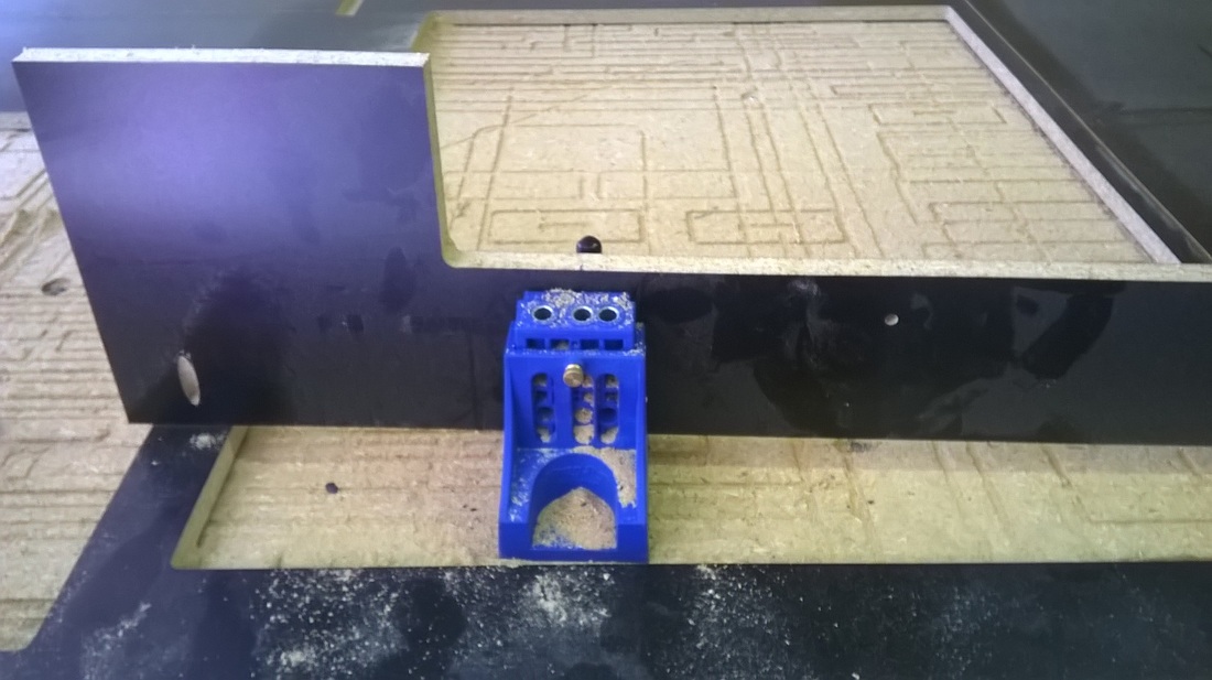
The first support I put in is for across the front of the cabinet. On the original plans, there is a small piece of wood in the center of the panel to allow the removable control panel to be installed by a screw. I added this panel to strengthen the front of the cabinet and to allow for something more substantial to hold the control panel down. I have pocket holes / screws that attach the panel to the sides and the front of the panel.
NOTE: The support panel is intentionally installed slightly below the edges of the cabinet. I wanted to make sure the control panel sat perfectly flat on the cabinet and would not be raised by the cross support.
The blocking that we previously installed and glued down in step #4 are primarily used as guides for placement and are not weight bearing. With that being said, the monitored supports are all installed with the pocket holes on the opposite side to the blocking. This way, when installed, the screws will pull the cross support towards the blocking allowing the blocking to provide additional strength as needed.
NOTE on materials: It is important that all of the monitor frame / mounts be cut from 3/4" plywood for strength purposes. Particle board, melamine, and MDF will not be strong enough to support a monitor.
The first support I put in is for across the front of the cabinet. On the original plans, there is a small piece of wood in the center of the panel to allow the removable control panel to be installed by a screw. I added this panel to strengthen the front of the cabinet and to allow for something more substantial to hold the control panel down. I have pocket holes / screws that attach the panel to the sides and the front of the panel.
NOTE: The support panel is intentionally installed slightly below the edges of the cabinet. I wanted to make sure the control panel sat perfectly flat on the cabinet and would not be raised by the cross support.
17. Next comes the cross support for the monitor base. With the slight indentations cut by CNC in the sides of the panel (.05"), the pieces just seems to jump in place. This is then screwed down in place.
NOTE: I did not drill any holes in this panel for the monitor mount. I would prefer to let the final installer perform this action to make sure placement is exactly correct per their monitor. It should also be noted that if the top and bottom monitor mounts need to be moved, they are designed to each have over an inch of movement. If they are misplaced, they can simply be unscrewed and then screwed down in their new position.
NOTE: I did not drill any holes in this panel for the monitor mount. I would prefer to let the final installer perform this action to make sure placement is exactly correct per their monitor. It should also be noted that if the top and bottom monitor mounts need to be moved, they are designed to each have over an inch of movement. If they are misplaced, they can simply be unscrewed and then screwed down in their new position.
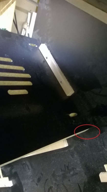
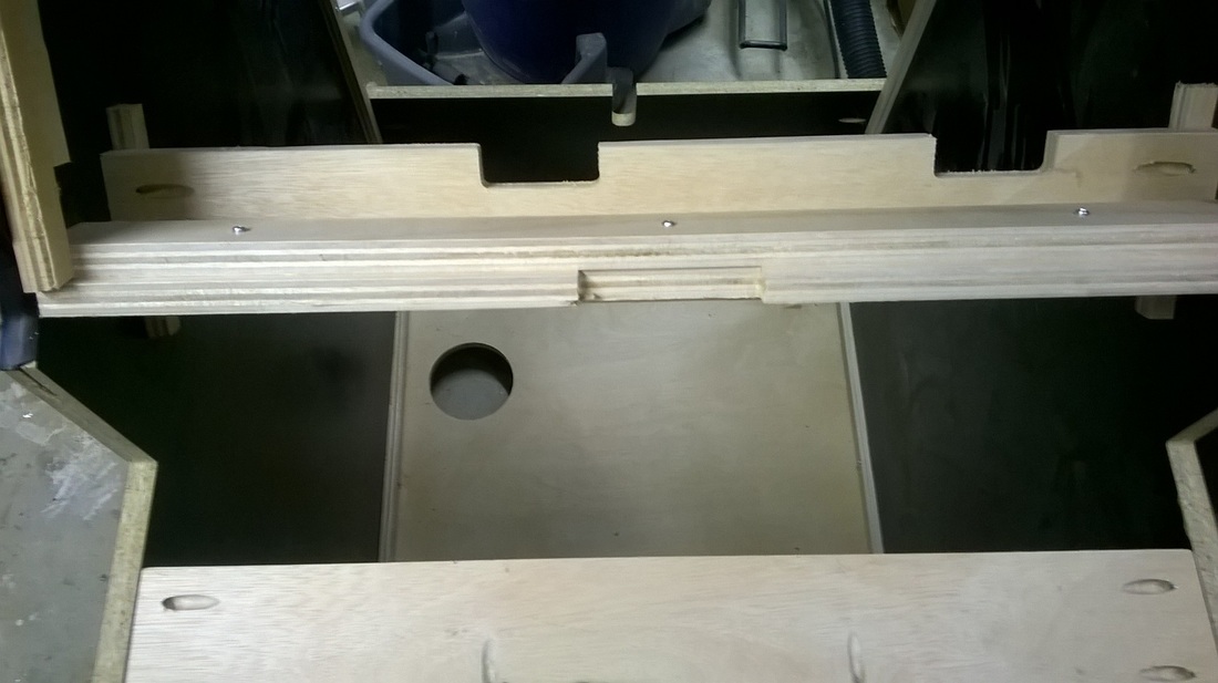
18. Next comes the cross support that holds the monitor glass. This panel also tends to jump into place due to the small guides cut into the side of the cabinet. The monitor glass support is also screwed into the monitor support to strengthen the panel (3 screws).
NOTE: A Piece of scrap wood is in the picture and is used to assist with alignment.
NOTE: A Piece of scrap wood is in the picture and is used to assist with alignment.
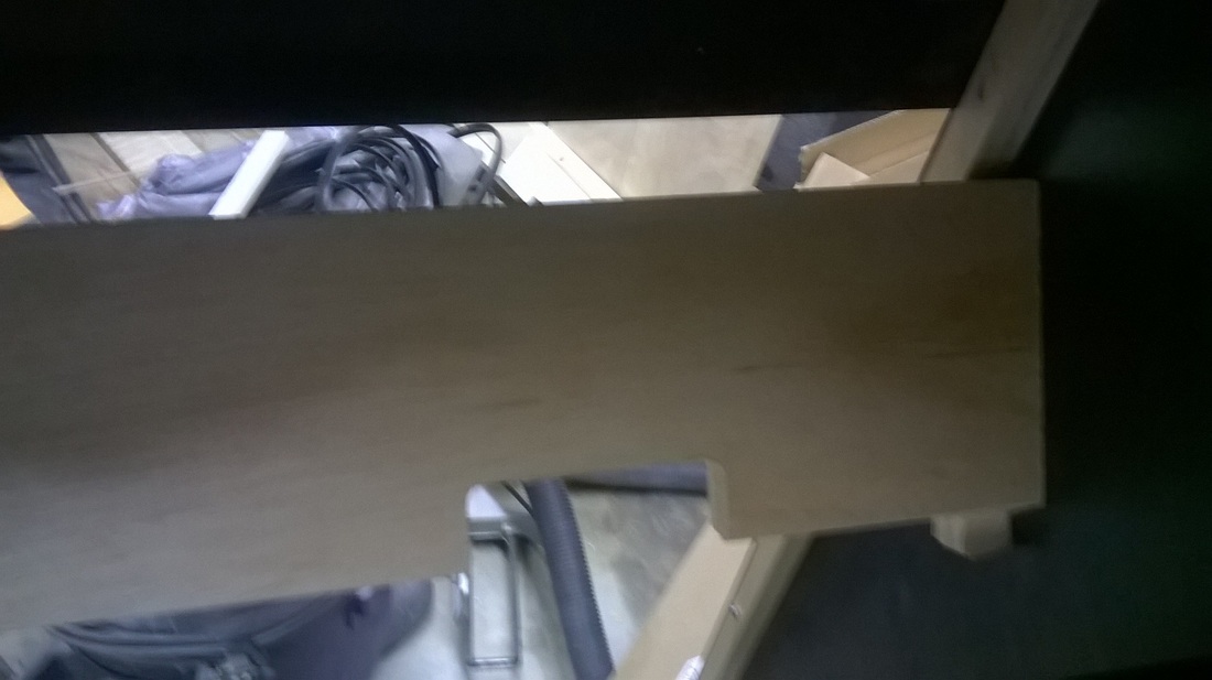
19. Add the final cross support for the top of the monitor. (Sorry for the poor picture)
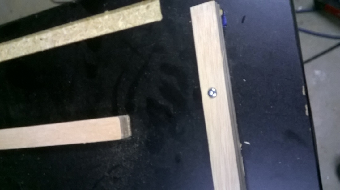
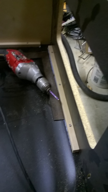
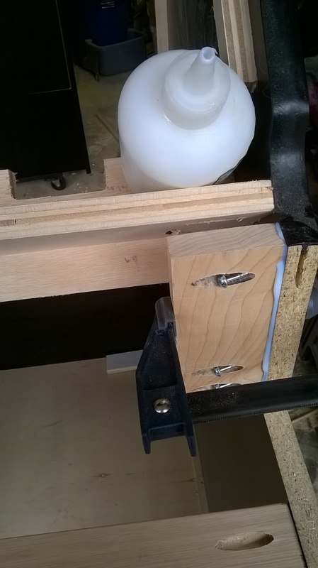
20. Next is to add a place for mounting supports for the control panel. The original plans use simple blocking that is stapled to support the control panel. I wanted something that was a little more robust. I cut a 1"x3" piece of maple (what I had lying around the shop), drilled 3 pocket holes per side, and commenced installing the supports. I put a coat of glue down, clamped the piece, and installed the 3 screws.
21. Next is the assembly of the control panel.
NOTE: I really hate the design / cuts of the control panel.... but I am true to the original design in this case. The original design are the plans posted to the website. Blocking and staple were originally used for assembly. I assembled with screw and glue. The pictures below are the order of assembly.
Sorry, but I don't have pictures of drilling the holes to attach the control panel to the main cabinet.
Using some glue, install and clamp the sides of the control panel. Repeat for the other side.
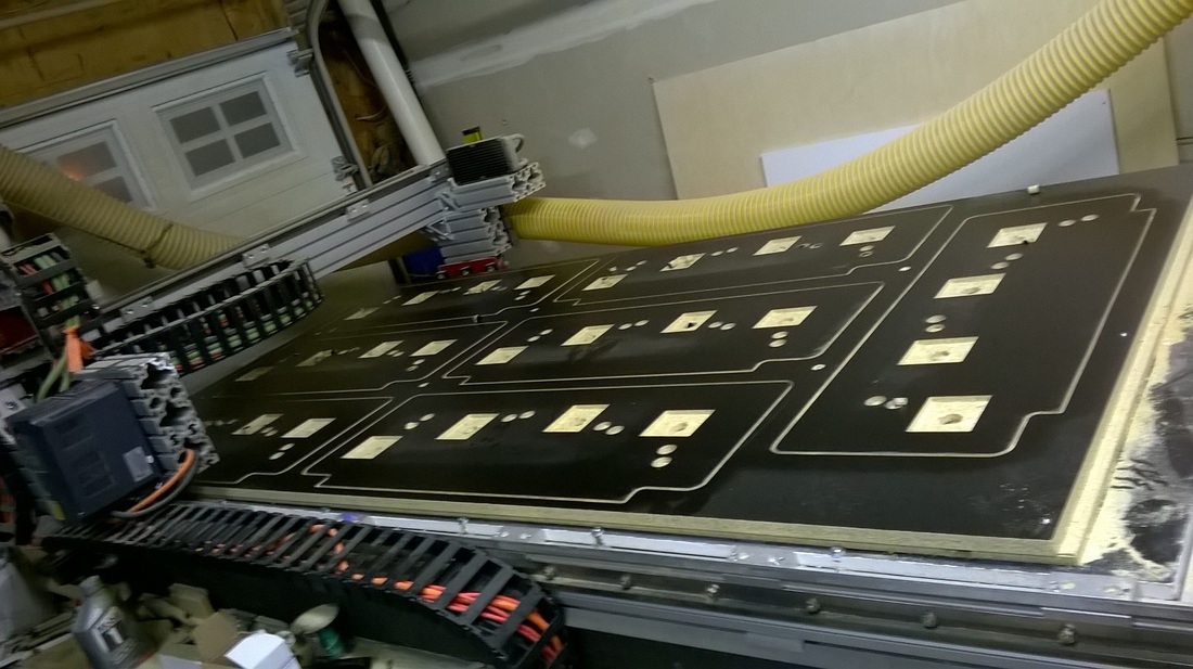
Cut a few TMNT / Simpsons control panels.
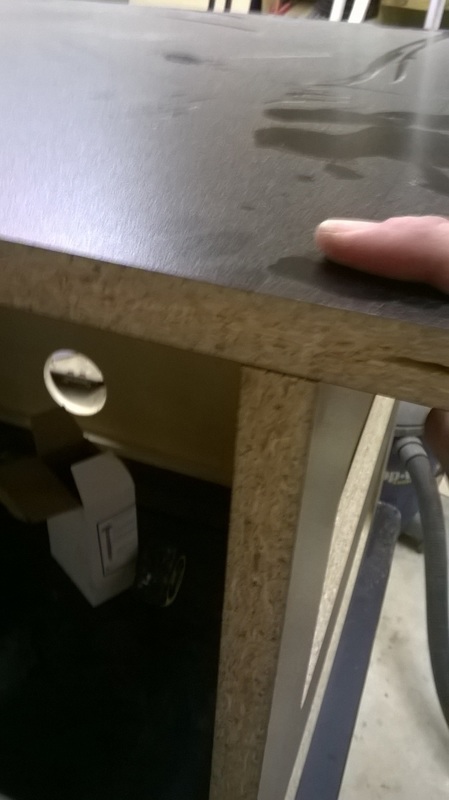
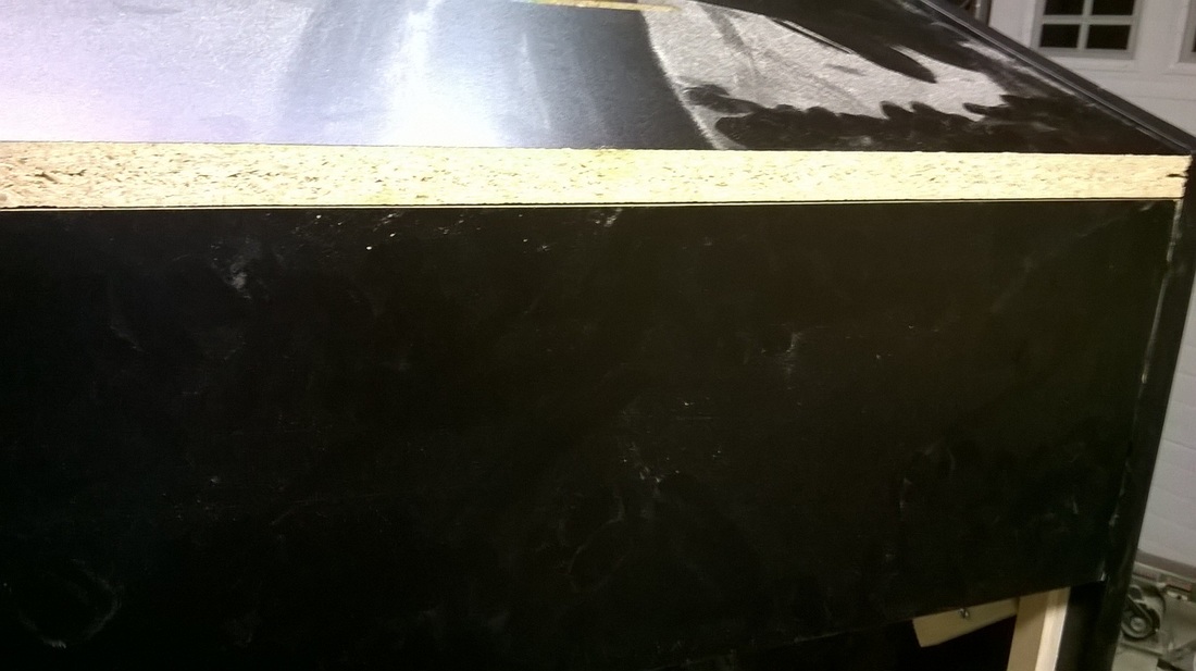
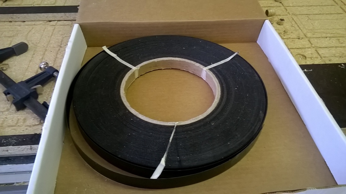
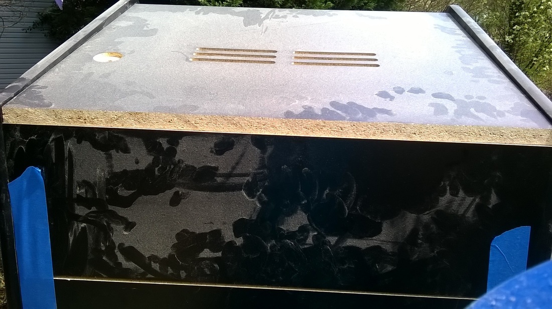
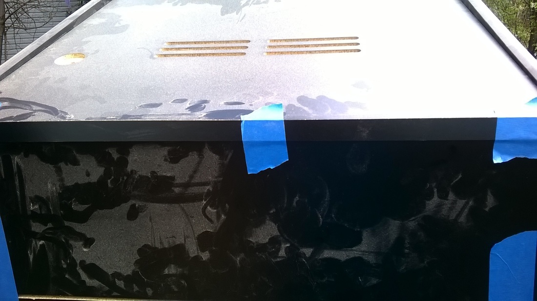
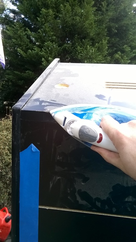
22. Now is the time for some "clean up". In this case, I am using 7/8" black melamine edge banding. I use this to cover up all of the exposed areas of cut melamine. This is mainly to help reduce the need to paint the exposed cuts.
The edge banding is applied with an iron and can easily be cut into any widths needed with scissors. I hole the edge banding in place with blue painters tape and heat it up with an iron until the glue on the back side melts.
The edge banding is applied with an iron and can easily be cut into any widths needed with scissors. I hole the edge banding in place with blue painters tape and heat it up with an iron until the glue on the back side melts.
|
|
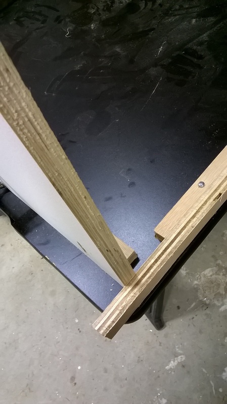
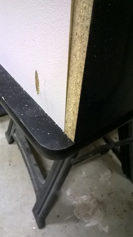
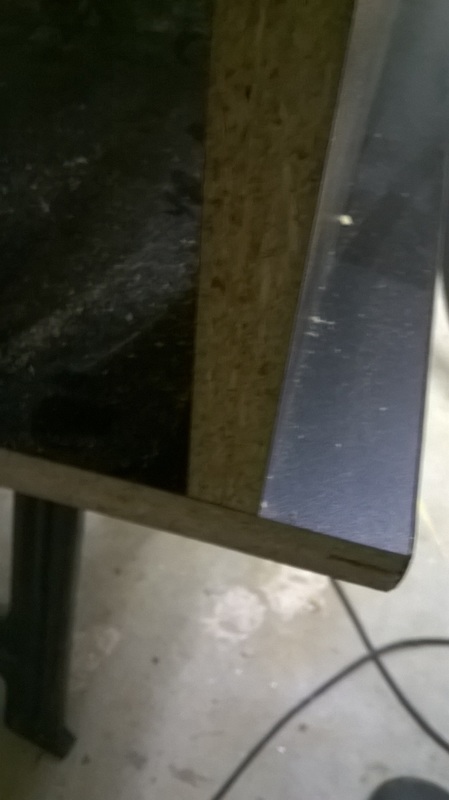
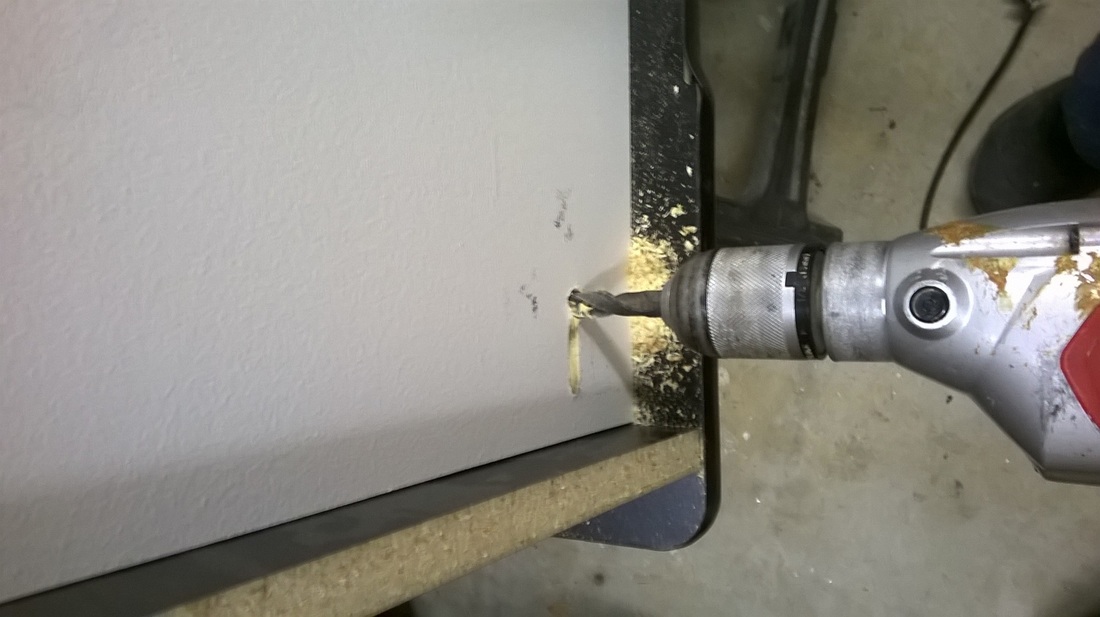
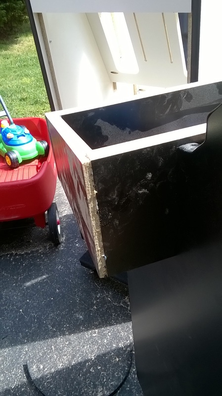
23. Final step for me is the cutting of the back door. This will tell you how square your assembly was.
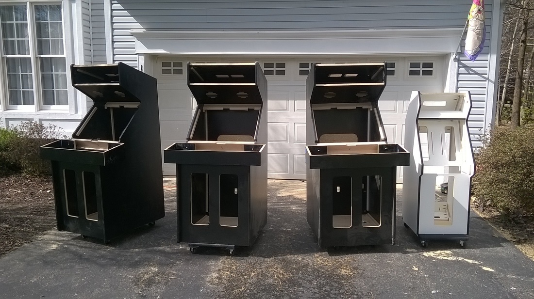
Picture of the final assembled cabinets for the weekend.
Hoped this guide helped. If anyone has any questions, please let me know and I will add in additional comments as needed.
Thank you
Thank you
Last updated 4/6/2016
|
|
Special thanks to the contribution by: Chris for the Pac-Man cocktail plans
All graphics/images/cabinet designs on this site are copyrighted by the their original owners. ClassicArcadeCabinets.com makes no claim to said such rights and provides the cabinet designs for collectors and hobbyist of the original arcade coin-op machines. Images and graphics are for reference only. Any copyright holder wanting their images or reproductions removed from this site should contact us and we will immediately remove these images.
SITE LAST UPDATED January 16, 2024
|

|