Drawing your cabinet in VCarve Pro
VCarve Pro will not allow you to transfer files between computers in DEMO mode.
Please note that the measurements below are fictional and are not accurate to a specific cabinet.
Open VCarve Pro and you will be presented with the below Welcome Screen. Select "Create a new file".
|
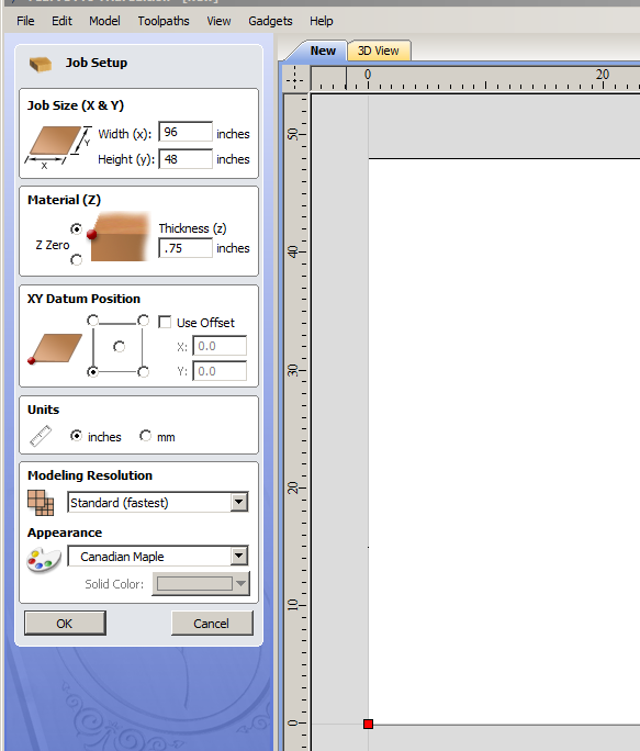
This will bring up one of the most important screens to understand for your drawings.
Job Size I set at X=96 and y=48 (standard plywood size), but it has no real relevance to your drawings. Likewise, I set Material thickness (Z) to .75" thick, but it also has no real relevance on your drawing. The most important thing to understand is the placement of the XY Datum Position. When you traced your cabinet and took measurements of the cabinet from the bottom back corner of the cabinet, you were taking length measurements (x axis) and height measurements (y axis). These measurements formed a pair (X,Y) of coordinates and reference back to your starting point of (0,0), the back base of your cabinet. The XY Datum Position is setting the position on your drawing to the bottom left hand side of your drawing... just like you set your (0,0) to the bottom back of the cabinet. All of your drawing point will reference this location. It is by default set to the lower left. Click OK. |
|
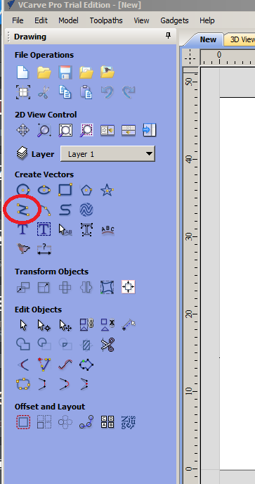
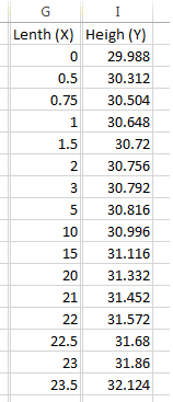
The menu to the left contains all of the drawing tools you will be using to create and save out your cabinet drawings. We are assuming that we will start drawing the side panels (most challenging part) of the cabinet first. You will do this by using the Draw line / Polyline tool. The measurements on the right are the coordinates / lengths you have previously measured. Please note that all measurements need to be in inches and converted to a decimal value (23 3/8" = 23.375). |
|
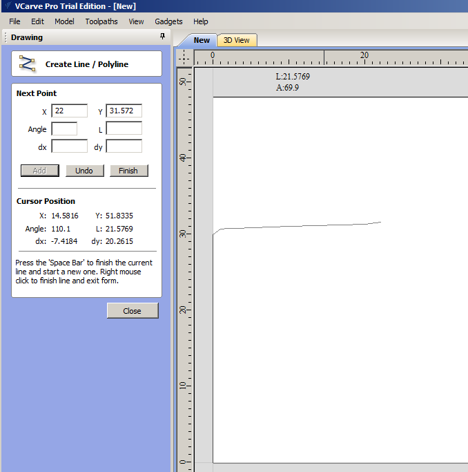
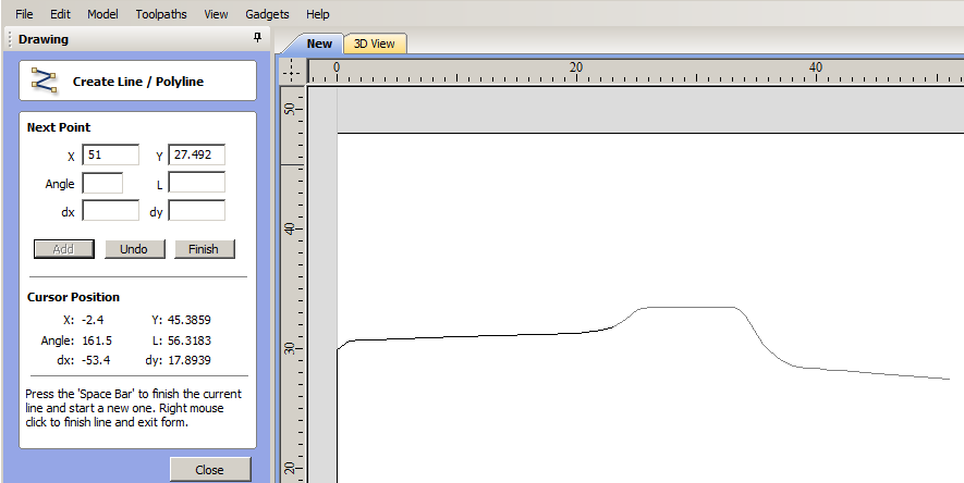
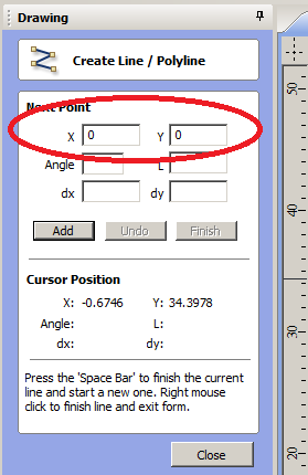
Using the Polyline tool, we start to enter in our lengths and heights starting with a (0,0) (X,Y). Click Add.
Then add your next point (0,29.988), Click Add, then (.5,30.212), Click Add, then (.75, 30.504), Click Add. For this howto, I am going to draw out the cabinet with less points (as someone who is not using a jig would be measuring a cabinet) and show you how to clean up some of the curves afterwards. |
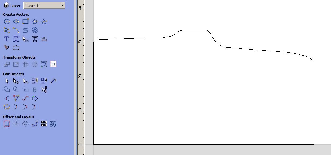
When you have entered all of your points, make sure you set your last point to (0,0). When you are done, you should have something that looks like the below.
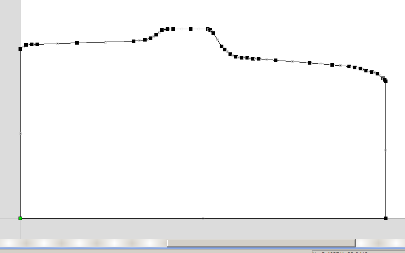
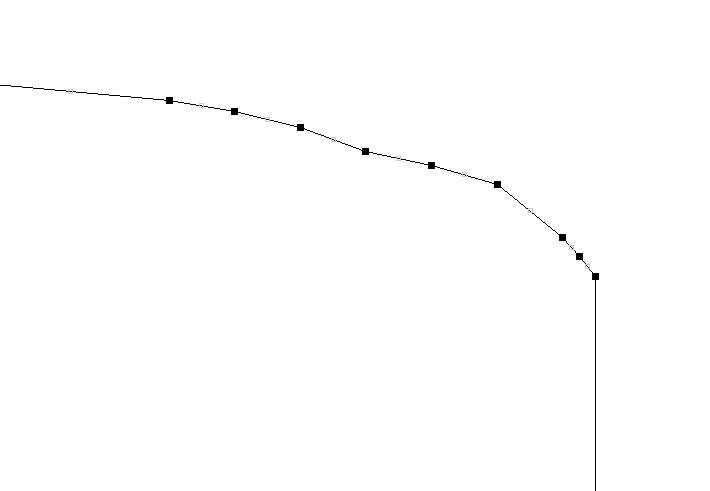
Next you will want to clean up some of your points. You can do this by right clicking on your drawing and go to "Node Edit mode". When you do, the drawing will change and show you all of the points you have entered in. See the drawing below.
As you look to start editing the points and curves, you need to consider if the curve is going to be a smooth transitioning curve, or a fixed radius curve.
If the curve is going to be a fixed radius curve (part of a circle), you will want your drawing to have a sharp point. These curves are most common at the corners for the cabinet (bottom front, bottom back, and top back). You will want to edit all of these to have only a single node with a sharp transaction. We will address these later.
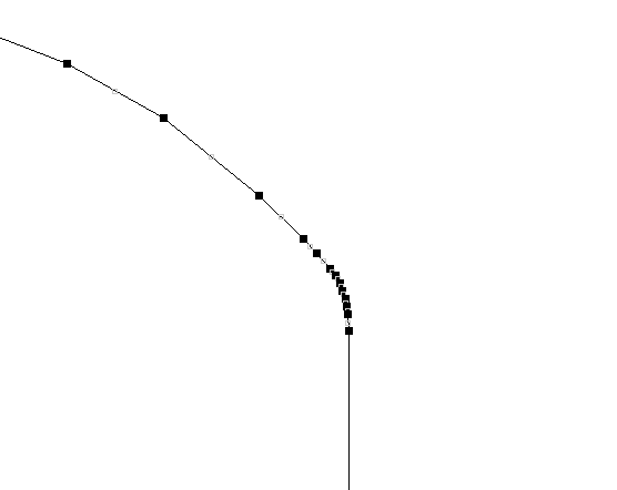
For the smooth transitions, we are going to want to fit a smooth transition between the nodes to create the smooth curve. The easiest way to do this is by zooming into a curve (place the pointer over the curve and wheel mouse scroll). You can now click on the nodes and move them around. If you only have a few measurements, I would leave your measured nodes in place. As you want to smooth out the corner, you can add additional nodes to start to smooth out the block line. You do this by simply right clicking on the line and clicking on "Insert node". I usually add nodes "mid span" between nodes until I am happy with the curve. You can continue to drill down and halve the vectors until you have a smooth transition. You have to be careful that you are not significantly changing the shape of your drawings.
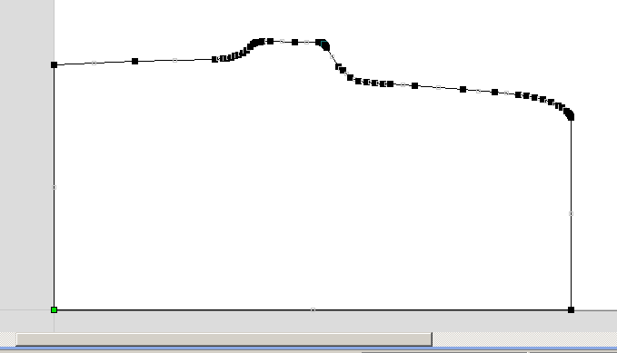
The next thing to do while in Node Edit mode is to delete the extra points along the straight edges. This can be difficult to decide on some cabinets because many of the "straight" edges have some type of transition or curve. You will have to use your best judgement if the variation was intentional or accidental in the cutting process. When you are all done, your drawing should look something like below. The majority of your nodes should be near the corners.
Next up is the fixed radius corners. These are much easier to draw in. First you need to determine what size radius you have. The easiest way is to gather up a number or round items and measure how large the circles are. Round lids make great measuring circles. Ideally, you should be able to find lids in 1" diameter increments. Next, place them on the cabinet and try and figure out what sizes you have. If it is between two, write it down as half inch increment.
|
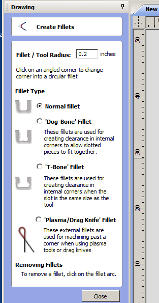
Next, click on the create fillets (to the left). This will bring up the Create Fillets menu.
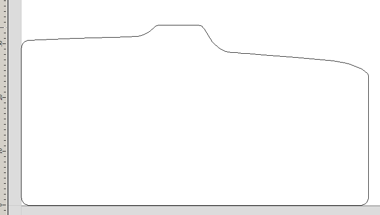
Enter in the radius of your corner (radius = 1/2 diameter). Make sure the Normal fillet is selected. With the menu still open, simply click on your corners and the drawings will have the curves corners automatically added. Also, please note that the corners do not have to be at 90 degrees to apply the fillet. The drawing should look like below. |
|
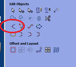
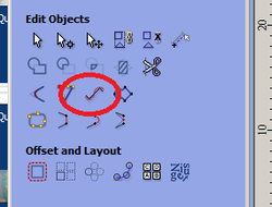
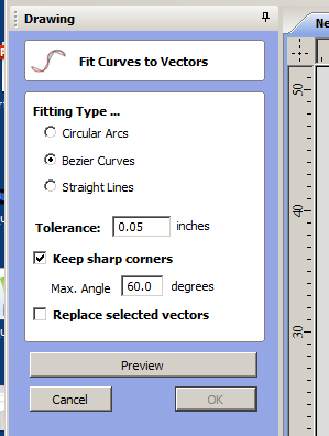
The next thing to do is to smooth out all of the edges. This is done by fitting a curve to the selected vectors. Select your cabinet side panel drawing and clicking on the "Fit curves to selected vectors" (See left).
With the menu up on the right, you will have to make sure your drawing is selected (in pink). Choose Bezier Curves and select a tolerance. You tolerance is how much the curve can be off the nodes you corrected earlier. The more nodes you add, the lower the tolerances you can have. When you are done, click preview. Areas you will want to look at are where a curve goes to a straight line to make sure you don't get a bulge in your drawings. |
With the exception of the blocking, you are basically done the side panel of the cabinet at this point.
|
Next up is to start to draw the remaining panels.
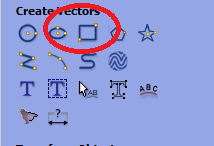
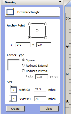
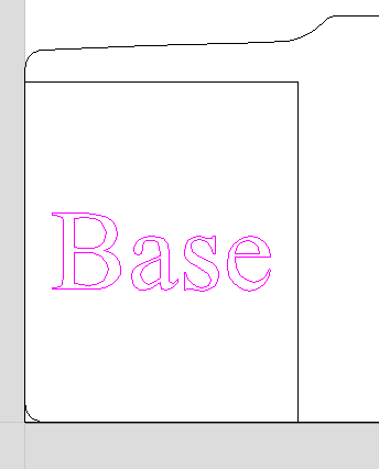
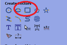
Starting out with the base, we draw a simple rectangle with the Draw Rectangle Tool (to the left). Next, you will need to choose your anchor point. I like to leave my anchor point a (0,0). In this case the base is 22.5" wide and 28" deep. When I am drawing out additional panels, I always leave the width of the panel on the X-axis. No real reason, it just seem to keep things more organized. |
|
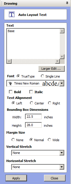
The text will be centered in the the box you have made.
|
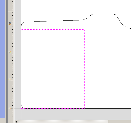
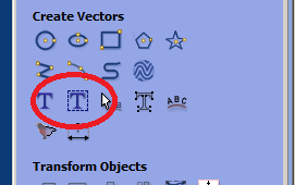
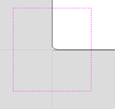
The base is drawn out with the bottom left hand corner being at (0,0). Please note that the base has been drawn on top of the side panels. This is not a big deal as each object is independent. The next thing to do is to place a label on the base so we do not get it confused with some other part of the cabinet. To do this, we select the "Draw text within a vector box" option. |
|
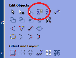
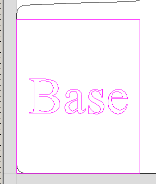
The next thing we will have to do is to link the text "Base" to the rectangular vector. This is important because it will allow is to move the vectors around and they will stay with the same relative position to each other. To do this, you need to select the rectangle and the text with your mouse. They will be highlighted with a pink dotted line. Then click on the group selected objects. This will lock the objects together so they move as a single object. When the objects are are locked together, they will have a solid purple line when selected.
With this completed, we can now move the base with label to some free space on the drawing by dragging it away from (0,0). |
|
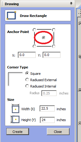
For the next component, we will consider a front panel that is 24" tall with a width of 22.5" and a coin door centered in the panel. When dealing with items that are centered inside each other, I change the drawing points for the center to be at (0,0). We start out with drawing a rectangle like we have previously. (left of the screen) The big difference this time is that we change the Anchor point to be in the center as opposed to the bottom left. (see drawing to the right) It results in the drawing below. |
|
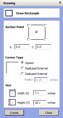
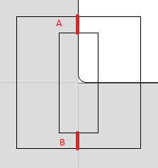
We then add another box for the coin door cutout. Using the same setting (anchor point at (0,0)), we enter in our dimensions of our coin door hole with a width of 7.1" and a height of 18. 1". The resulting drawing is to the far right. If the coin door is not centered in the front panel, you will need to measure the distance from the top of the hole to the top of the front panel (A), and the distance from the bottom of the hole to the bottom of the panel (B). Your new anchor point would be X=0, Y=(A-B)/2 |
Once you have the panel and coin door where you want it, the next thing to do is to group the two items together and put a label on them. Once completed, you can move the item away from the (0,0) coordinate.
More to follow...
Last updated 8/31/2015
|
|
Special thanks to the contribution by: Chris for the Pac-Man cocktail plans
All graphics/images/cabinet designs on this site are copyrighted by the their original owners. ClassicArcadeCabinets.com makes no claim to said such rights and provides the cabinet designs for collectors and hobbyist of the original arcade coin-op machines. Images and graphics are for reference only. Any copyright holder wanting their images or reproductions removed from this site should contact us and we will immediately remove these images.
SITE LAST UPDATED January 16, 2024
|
