|
Arcade - Arcade Cabinets - Nintendo - Radar Scope Straight Front
Radar Scope Straight Front
Misc. Information
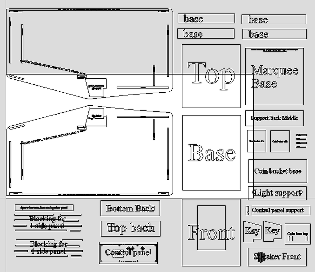
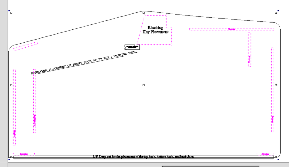
Cabinet measurements provided by: anonymous Has a cabinet been cut from drawings: Construction type: 15mm plywood Estimate Cabinet Accuracy =80% General measurements on cabinet verified. What does Cabinet Accuracy mean? I am not sure really how I should judge this one. The plans are basically a standard Nintendo cabinet with the correct measurements for the side panels and other components. Thanks to KLOVer MikeHoss1414 for taking the measurements. With that said, the internal structure for mounting the "TV" is not represented in the drawings. There is a line representing the approximate placement on the front edge of the TV cabinet / monitor shroud. See the attached reference photos. I am not sure how relevant this placement is. I believe the drawings will allow for the creation of a Nintendo cabinet that will allow for the Marquee, control panel, etc... to fit, and the cabinet will look authentic, but the individual components would not be interchangeable between the drawing below and an original cabinet. |
|
Picture of finished cabinet - N/A
Sketch Up
|
Not available.
|
VCarve Pro drawing
VCarve Pro (Verson 8.024) file
Note: .CRV files do not contain tool paths.
| nintendo__old_straight_front_-_revision_2.crv | |
| File Size: | 2703 kb |
| File Type: | crv |
DXF File (CAD file.)
| nintendo__old_straight_front_-_revision_2.dxf | |
| File Size: | 15549 kb |
| File Type: | dxf |
Files to Print
The below files are PDF documents of the plans that are printed to scale. These documents can be taken to your local print shop and printed on 36" wide media. The prints can then be applied to the wood and used as a template to cut the side panels of the cabinet. I have only included the side panels and any other panels that may be more difficult to cut.
| radar_scope_flat_front.pdf | |
| File Size: | 67 kb |
| File Type: | |
Cabinet Art Files
Currently not available
Reference Photos
Special thanks to KLOVer mikehoss1414 for the reference photos.
Drawing specific notes
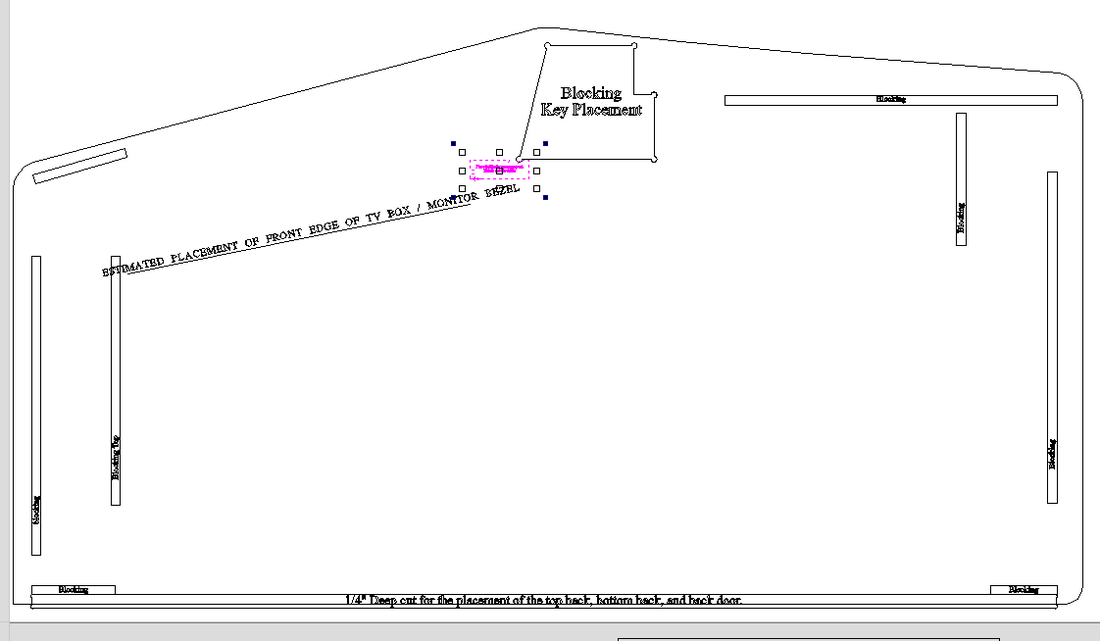
A couple of note to help clarify the drawings. The areas below highlighted in pink represent the placement of blocking on the side panels. This is to assist with the assembly of the cabinet. There is no need to make any cuts for the placement of the blocking, but if you have access to a CNC, you can make a shallow .05" to .1" cut to help with the assembly with the blocking.
The items highlighted in pink below are only on the drawings for reference. The have been added to the drawings to help assist with assembly. They do not require any cuts.
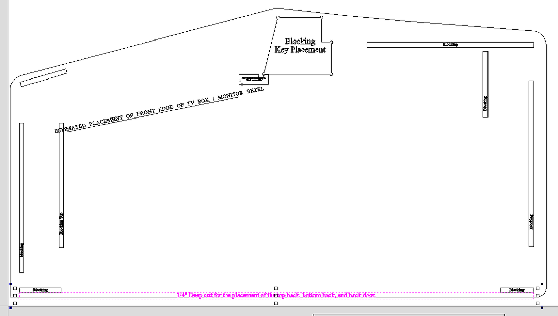
The item below highlighted in pink is a pocket cut of 1/4". This is for the back door and the assembly of the "Top Back" and "bottom back".
Comments
3/17/2016 - Plans were updated to reflect corrections made to the back of the cabinet and identification of placement and blocking structure.
Last updated 3/17/2016
|
|
Special thanks to the contribution by: Chris for the Pac-Man cocktail plans
All graphics/images/cabinet designs on this site are copyrighted by the their original owners. ClassicArcadeCabinets.com makes no claim to said such rights and provides the cabinet designs for collectors and hobbyist of the original arcade coin-op machines. Images and graphics are for reference only. Any copyright holder wanting their images or reproductions removed from this site should contact us and we will immediately remove these images.
SITE LAST UPDATED January 16, 2024
|

